The Topology Relational Model Transform generates a special transform that produces a data structure used by Topology Visualizations. The current Topology Relational Model assumes a relationship between multiple tabular datasets. By describing these relationships, the model produces parent and child linkages that Topology Visualizations can consume to display.
Create a Relational Model Transform
- Select the
 icon for a node
 - Select the “Transform” option from the context menu.
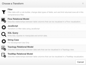
The “Choose a Transform” dialog will appear, showing the available transforms in the system. Select the “Topology Relational Model” option. This will launch the Relational Model Wizard:
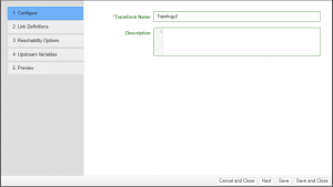
Relational Model Wizard
Step 1: Configure
| Property | Description |
|---|---|
| Name | A symbolic name used to represent this transform. This is the name that will show up in the pipeline node representing this transform. |
| Description | This is where the administrator can enter notes for the transform. |
Step 2: Link Definitions
| Property | Description |
|---|---|
| Link Definitions | A graphical editor for defining the relationships between multiple tabular datasets. The instructions to use this editor are provided below. |
| Node Unique Columns | The selected data attributes that uniquely defined a data set in the model. This is important when you have Topology Visualizations off of this model with a setting of ‘only show nodes approved by the administrator’. |
Working with the Link Definitions Editor
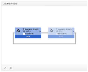
The Link Definitions Editor is seeded with the node from which you created the Relational Model transform.
- Use the button on a node to add a relationship to another tabular dataset.
- Use the ‘Hide Node’ checkbox to hide a node from any end visualization. This is useful when working with a lookup table, a dataset that just contains linkages and is not intended for display.
The illustration above is a self-referential example, where parent and child nodes can be in the same dataset. In other cases, different datasets can be the parents and children in the relationship.
Adding a Link Definition
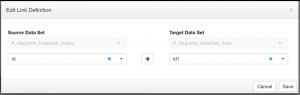
When configuring a link definition, select two data sets:
- A “Source” Data Set
- A “Target” Data Set
The two datasets must contain an attribute with values that link the two datasets together. This is similar to choosing foreign keys in a SQL Join statement. Both attributes MUST be of the same data type.
The Arrow in the middle is a clickable button. This button allows you to change the direction of the relationship, or to select non-directional.
Editing a Link Definition
To make changes to a relationship that already exists, click a Link between two nodes in the relational model, and then click the ![]() edit button or double click the link.
edit button or double click the link.
Editing a Data Set’s unique columns
To make changes to a data set’s unique columns, click a node in the relational model, and then click the ![]() edit button or double click the node.
edit button or double click the node.
Step 3: Reachability Options
Reachability options determine how nodes are discovered. By default, the nodes that are displayed include:
-
- All visible nodes designated as root nodes in the relational model.
- All visible nodes that can be reached by traversing links from root node.
Direction definition: For the purpose of node discovery, “down” is in the direction of the “Target Data Set” nodes as defined in the “Link Definitions”, and “up” is in the direction of the “Source Data Set”.
The reachability options provide the following customizations:
- Only lineal nodes
- Discovery from root nodes should only occur in a single direction
- Example: If the first link followed was down, further discovery along that path will only be down. This is often used with hierarchical data when all descendants or ancestors of a starting node are desired.
- Limit number of hops/links in discovery. Either:
- Limit max total hops: Number of links followed from root nodes cannot exceed this number
- Limit hops up and down: Number of links followed up vs. down from root nodes will be counted separately. This is useful if you desire all ancestor nodes in a hierarchy, but only a single level of descendants.
Step 4: Upstream Variables
Details about this step can found here: Satisfy Upstream Node Variables Wizard Step.
Step 5: Variables
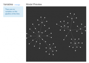
The last step of the wizard allows you to manage Variables and is also a preview. It shows a simple diagram of nodes and links that represent the relationships you just defined. If you are familiar with the data you are trying to show, it can be useful in seeing if you correctly described the relationships. You would also use the sidebar of this wizard to modify upstream variables if needed.